
Page 39 - 艾博母线有限公司
P. 39
试验条件
Test conditions
温升条件:应符合GB/T 9978-1999中5.1的规定。
压力条件: 应符合GB/T 9978-1999中5.2的规定。
受火条件:试件为四面受火,实际工程有特殊要求的除外。
试件要求:试件为三相四线制或三相五相制直线形母线干线耐火单元,受火段长度至少为4m, 并含有一个接头。
Temperature rise condition: it should meet the requirement of 5.1 in GB/T 9978-1999.
Pressure conditions: shall comply with the provisions of 5.2 in GB/T 9978-1999.
Fire condition: the specimen is exposed to fire on all sides, except for special requirements in practical engineering.
Test piece requirements: the test piece is a fire resistant unit of three-phase four-wire or three-phase five-phase bus main line, with a length of
at least 4 m and a joint.
安装
a)试件两端支承在耐火试验炉炉璧上,两端伸出试验炉长度均不小于500mm。并用不燃性隔热材料封堵两端。
b)应使试件接头处在炉中间,在接头两侧各设置一个支撑,并保持其间距不小于1000 mm,该支撑由试验单位统一提供,并使
炉顶距试件的距离不小于150mm。试件炉内安装简图见图3
The installation
A) both ends of the specimen are supported on the round of the refractory test furnace, and both ends extend out the length of
the test furnace not less than 500mm. Seal both ends with non-combustible heat insulation material.
B) the specimen joint shall be placed in the middle of the furnace, and a support shall be provided on both sides of the joint, and
the spacing shall not be less than 1,000mm, which shall be provided uniformly by the test unit and shall be maintained The distance
between the top of the furnace and the specimen is not less than 150mm. See figure 3 for the brief installation diagram of the
sample furnace 单位为毫米
1 2 3 4
millimeters:mm
1 耐火 试验炉
Fire test furnace
2 试件
specimen
3 接头
joint
4 支承
bearing
1000
≥500 ≥500
图3 试件炉内安装简图
FIG. 3 brief installation diagram of sample furnace
注.应保证支撑在耐火时间内不失去承载能力。
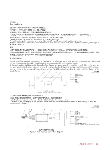
c)为了检验试件线路的完整性,应进行必要的电气连接,连接简图见图 4
Note. The bearing capacity of the support shall not be lost in the fire resistance time.
C) in order to test the integrity of the test piece circuit, necessary electrical connections should be made. See figure 4 for the
connection brief diagram
单位为毫米
millimeters:mm
1 2 3 4 5 6
1 变压器
transformer
2 熔断器(2A)
L3 L3 Fuse (2 a)
L2 L2 连接到L3(或L2或L1)
L1 L1 3 Connect to L3(or L2 or L1)
N
PE 4 试件
specimen
5 母线排
Bus line
6 负载和指示装置(如灯泡)
Load and indication devices (such as light bulbs)
图4 试验电气连接图
Figure 4 Test electrical connection diagram
INTENSIVE BUSWAY 38